如何使用 I2C LCD2004 範例與教學 Arduino 與 Raspberry Pi 樹莓派教學
眾所周知,雖然 LCD 和一些其他顯示器大大增強了人機互動,但它們也有一個共同的缺點:當它們連接到控制器時,會佔用多個 IO 端口,而許多控制器並沒有那麼多外部端口,這也限制了控制器的其他功能。因此,採用 I2C 總線的 LCD2004 被開發出來以解決這個問題。
I2C 總線是一種由飛利浦(PHILIPS)發明的串行總線,它是一種高效的串行總線,具備多主機系統所需的總線規則和高、低速設備同步功能。I2C 總線僅需兩條雙向訊號線,即串行數據線(SDA)和串行時鐘線(SCL)。I2C LCD2004 上的藍色電位計用於調整背光亮度,使其更容易在 I2C LCD2004 上顯示內容。
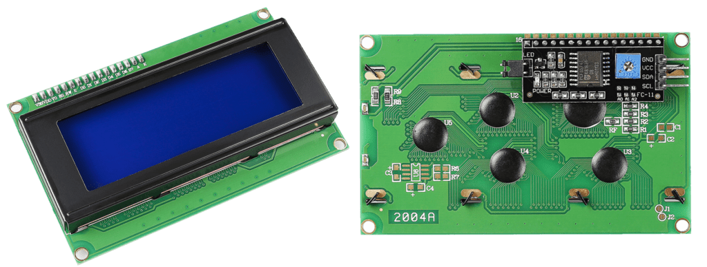
- GND:接地
- VCC:電源供應,5V
- SDA:串行數據線。通過上拉電阻連接至 VCC
- SCL:串行時鐘線。通過上拉電阻連接至 VCC
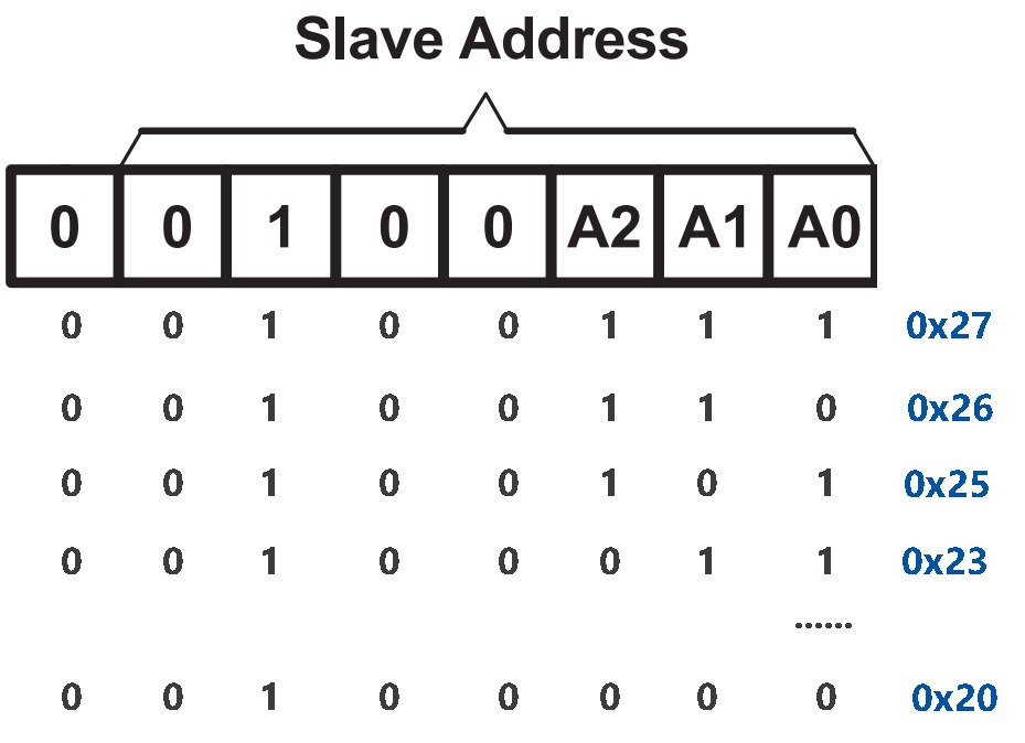
I2C 位址
預設位址基本上為 0x27,但在某些情況下可能為 0x3F。
以預設位址 0x27 為例,可以通過短路 A0/A1/A2 焊點來修改裝置位址;在預設狀態下,A0/A1/A2 為 1,若焊點被短接,A0/A1/A2 將變為 0。
背光/對比度
可以透過跳線帽來啟用背光,拔下跳線帽則會關閉背光。背面的藍色電位計用於調整對比度(最亮的白色與最暗的黑色之間的亮度比例)。
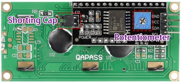
- 短路帽:可用於啟用背光,拔下此帽則會關閉背光。
- 電位計:用於調整對比度(顯示文字的清晰度),順時針方向增加對比度,逆時針方向減少對比度。
Arduino 使用者
元件清單
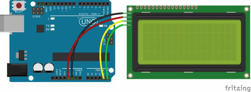
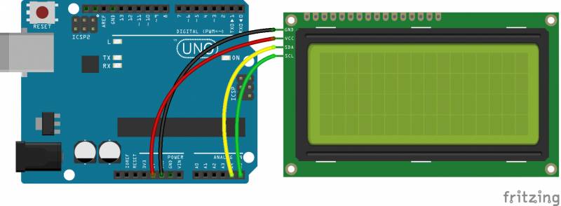
連接電路
請參考下表,將 I2C LCD2004 模組與 Arduino Uno 開發板進行連接:
添加程式庫
在將程式碼上傳到控制板之前,您需要添加 LiquidCrystal_I2C 程式庫。
- 下載 LiquidCrystal_I2C 程式庫
- 打開 Arduino IDE,選擇「草圖」->「包含程式庫」->「加入 ZIP 程式庫」
- 找到您剛剛下載的 LiquidCrystal_I2C 文件,點擊打開。隨後會看到提示「已將程式庫添加至您的程式庫。請檢查『匯入程式庫』」。您也可以在「草圖」->「包含程式庫」->「LiquidCrystal_I2C」列表中看到剛剛匯入的程式庫。
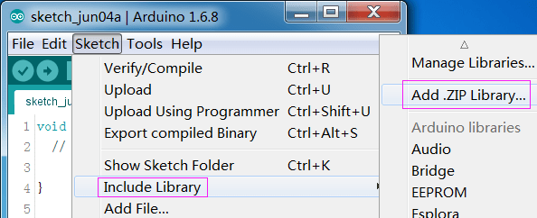
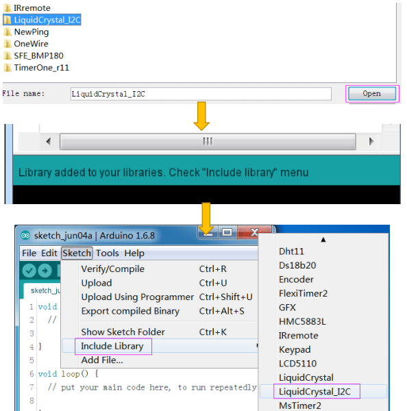
複製程式碼
將以下程式碼複製到 Arduino IDE 中:
1 2 3 4 5 6 7 8 9 10 11 12 13 14 15 16 17 18 19 20 21 22 23 24 25 26 27 28 29 30 31 32 33 34 35 36 37 38 39 40 41 42 43 44 |
/***************************************** * name: I2C LCD2004 * function: You should now see your I2C LCD2004 display "Hello,world!","IIC/I2C LCD2004" * "20 cols, 4 rows","www.sunfounder.com" ********************************/ //Email:service@sunfounder.com //Website:www.sunfounder.com /********************************/ // Include necessary libraries #include <Wire.h> #include <LiquidCrystal_I2C.h> // Initialize the LCD object, set the LCD I2C address to 0x27 for a 20x4 display LiquidCrystal_I2C lcd(0x27, 20, 4); /*********************************************************/ void setup() { lcd.init(); // Initialize the LCD lcd.backlight(); // Turn on the backlight // Set cursor to the top left corner and print the string on the first row lcd.setCursor(0, 0); lcd.print(" Hello, world! "); // Move to the second row and print the string lcd.setCursor(0, 1); lcd.print(" IIC/I2C LCD2004 "); // Move to the third row and print the string lcd.setCursor(0, 2); lcd.print(" 20 cols, 4 rows "); // Move to the fourth row and print the string lcd.setCursor(0, 3); lcd.print(" www.sunfounder.com "); } /*********************************************************/ void loop() { // Empty loop } /************************************************************/ |
上傳程式碼
在上傳程式碼之前,請確保選擇正確的開發板和連接埠,請按照以下步驟操作:
- 點擊「工具」->「開發板」,然後選擇「Arduino/Genuino Uno」。

2. 接著選擇「工具」->「連接埠」。
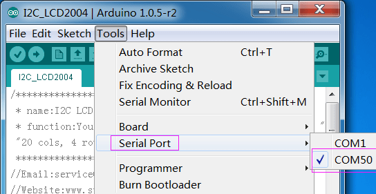
3. 點擊上傳圖示,將程式碼上傳到控制板。
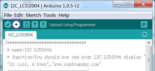
如果視窗底部出現「上傳完成」,表示程式已成功上傳。
讀取 I2C 位址 I2C_Scan
如果一切正常,但顯示屏僅在第一行顯示 16 個黑色方格,這可能表示 I2C 位址並非 0x27,因此您需要運行以下程式碼來讀取位址,然後將 0x27 修改為讀取到的位址。
|
|
LiquidCrystal_I2C lcd(0x27,16,2); |
1 2 3 4 5 6 7 8 9 10 11 12 13 14 15 16 17 18 19 20 21 22 23 24 25 26 27 28 29 30 31 32 33 34 35 36 37 38 39 40 41 42 43 44 45 46 47 48 49 50 51 52 53 |
/***************************************************** * Name: I2C_Address * Function: Read the address of the I2C LCD1602 * Connection: * I2C Arduino UNO * GND GND * VCC 5V * SDA A4 (pin 20 in Mega2560) * SCL A5 (pin 21 in Mega2560) ********************************************************/ #include <Wire.h> // Include Wire library for I2C communication void setup() { Wire.begin(); // Initialize I2C communication Serial.begin(9600); // Start serial communication at 9600 baud rate Serial.println("\nI2C Scanner"); // Print a message to the serial monitor } void loop() { byte error, address; // Declare variables for storing error status and I2C address int nDevices; // Variable to keep track of number of devices found Serial.println("Scanning..."); // Print scanning message nDevices = 0; // Initialize the device count to 0 // Loop through all possible I2C addresses (1 to 126) for (address = 1; address < 127; address++) { Wire.beginTransmission(address); // Start a transmission to the I2C address error = Wire.endTransmission(); // End the transmission and get the status // Check if device responded without error (acknowledged) if (error == 0) { Serial.print("I2C device found at address 0x"); // Notify device found if (address < 16) Serial.print("0"); // Print leading zero for addresses less than 16 Serial.print(address, HEX); // Print the address in hexadecimal Serial.println(" !"); nDevices++; // Increment the device count } else if (error == 4) { // If there was an unknown error Serial.print("Unknown error at address 0x"); // Notify about the error if (address < 16) Serial.print("0"); // Print leading zero for addresses less than 16 Serial.println(address, HEX); // Print the address in hexadecimal } } // After scanning, print the results if (nDevices == 0) Serial.println("No I2C devices found\n"); // No devices found else Serial.println("done\n"); // Scanning done delay(5000); // Wait 5 seconds before the next scan } |
Raspberry Pi 樹莓派使用教學
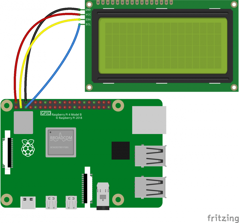
設定 I2C
啟用您的 Raspberry Pi 的 I2C 埠(如果已經啟用,請跳過此步驟;如果不確定是否已啟用,請繼續進行)。
步驟 1:運行以下指令。
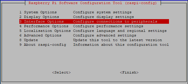
步驟 2:選擇「3 接口選項」
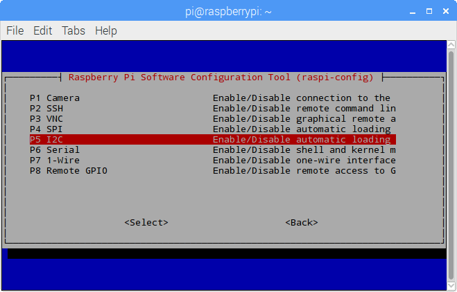
步驟 3:選擇「P5 I2C」。
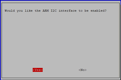
步驟 4:選擇「<Yes>」,然後「<Ok>」 -> 「<Finish>」。
步驟 5:檢查 I2C 模組是否已加載並啟用。
步驟 6:接著將出現以下代碼(數字可能會有所不同)。
|
|
i2c_dev 6276 0 i2c_bcm2708 4121 0 |
步驟 7:安裝 i2c-tools。
|
|
sudo apt-get install i2c-tools |
步驟 8:檢查 I2C 裝置的位址。
|
|
i2cdetect -y 1 # For Raspberry Pi 2 and higher version |
|
|
i2cdetect -y 0 # For Raspberry Pi 1 |
|
|
pi@raspberrypi ~ $ i2cdetect -y 1 0 1 2 3 4 5 6 7 8 9 a b c d e f 00: -- -- -- -- -- -- -- -- -- -- -- -- -- 10: -- -- -- -- -- -- -- -- -- -- -- -- -- -- -- -- 20: -- -- -- -- -- -- -- 27 -- -- -- -- -- -- -- -- 30: -- -- -- -- -- -- -- -- -- -- -- -- -- -- -- -- 40: -- -- -- -- -- -- -- -- -- -- -- -- -- -- -- -- 50: -- -- -- -- -- -- -- -- -- -- -- -- -- -- -- -- 60: -- -- -- -- -- -- -- -- -- -- -- -- -- -- -- -- 70: -- -- -- -- -- -- -- -- |
如果已連接 I2C 裝置,則會顯示該裝置的位址。
步驟 9:安裝 libi2c-dev 或 smbus。
適用於 C 語言使用者
|
|
sudo apt-get install libi2c-dev |
適用於 Python 使用者
下載並運行程式碼
步驟 1:下載程式碼包。
|
|
wget https://www.taiwansensor.com.tw/wp-content/uploads/2024/11/I2c_lcd2004_for_raspberry_pi.zip |
步驟 2:解壓縮程式碼包。
|
|
unzip I2c_lcd2004_for_raspberry_pi.zip |
(適用於 C 語言使用者)
步驟 3:如果尚未安裝 wiringPi,您需要先進行安裝。
|
|
sudo apt-get update git clone https://github.com/WiringPi/WiringPi cd WiringPi ./build |
步驟 4:您可以通過以下指令來測試 wiringPi 程式庫是否成功安裝。
步驟 5:進入程式碼的資料夾。
|
|
cd ~/I2c_lcd2004_for_raspberry_pi/c |
步驟 6:編譯程式碼。
|
|
gcc lcd2004.c -o lcd2004 -lwiringPiDev -lwiringPi |
步驟 7:運行程式。
(適用於 Python 使用者)
步驟 3:進入程式碼的資料夾。
|
|
cd ~/I2c_lcd2004_for_raspberry_pi/python |
步驟 4:運行程式。
|
|
sudo python lcd2004_show.py |






發佈留言
很抱歉,必須登入網站才能發佈留言。